I thought maybe someone might find this useful. Here are gerber files for a multi channel switcher PCB: http://ghr.fi/tube/switcher/multichanne ... gerber.zip. It's a 2 layer PCB sized 74mm X 42mm.
Nice work... but I don't know how excited I should be. Do you have a link for the circuit description from Merlin?

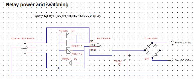
I just incorporated this very circuit into a piece of amp production equipment (to toggle amps on burn-in rack to monitor speaker outputs at o-scope)
E3 Channel Switch
The gist of it is when a button is pressed a relay driver transistor turns on. Only one transistor will be on at a time.
You can find a description of how this kind of a circuit works here http://sound.whsites.net/project163.htm. Just scroll down to where it says Discrete CMOS Logic.
Dorrisant wrote: ↑Wed Sep 05, 2018 4:02 pm Nice work... but I don't know how excited I should be. Do you have a link for the circuit description from Merlin?
A/b Box Switch 2 Inputs 1 Output With Dual Op Amps
V2 wrote: ↑Tue Dec 04, 2018 12:06 am What is V+ for this circuit? Maximum recommended supply voltage for 40175 is 15V. V+ can be anything from 5V to 15V. Most likely you will want to use either 5V or 12V depending on what relays you're using.
Interesting project. Can individual switches be turned off, like pedal? So you have radio button option between 4 switches and option to bypass all?
I’ve had some of these made and in the next few weeks will incorporate into a 4 channel amp, so will report back.
Diy 6v6 Se Ul Tube Amplifier Schematic
Quick question: can 2 of these chips be used simultaneously for 8 channels? Wondering how the flip/flop reset would work in this instance
Kdmay wrote: ↑Mon Apr 29, 2019 1:00 am Quick question: can 2 of these chips be used simultaneously for 8 channels? Wondering how the flip/flop reset would work in this instance Yes. We used this circuit for a set of amp monitoring and burn-in units in mfg....with two of these circuits per unit (8ch) and linked for a total of 24 ch...just connnect the CLK pins together.
Haven't tested more than that. Might need bi-directional buffer between CLK circuit sets if cable L get too long. We just use std midi cables to link clk and audio. Also used CD40xx buffers to drive relays...but I would use 2N7000 or similar to lo-side switch relays and LEDs for anything under 8ch. Also, DON'T share your relay logic gnd w/ your audio gnd.....reference terminate it at chassis common.

How To Build An Audio Mixer
Yes. We used this circuit for a set of amp monitoring and burn-in units in mfg....with two of these circuits per unit (8ch) and linked for a total of 24 ch...just connnect the CLK pins together.
In the amp build I mentioned I am trialling this, I am definitely not going to share the logic ground with the audio ground. A buddy did this with one of the Tube Town Midi boards and had all sorts of troubles so had already warned me on this.It is pretty much standard fare that guitar amps will have effects and/or different channels that need to be switched - often in the middle of a song. Running long leads from the amp to a pedal board is one way, but that's almost designed to pick up noises and affect the top end. Relays are used in some amps, but while these are almost perfect switches, they are also a cause for much grief in a combo amp. The vibrations from the speaker can often cause the relay contacts to 'chatter', and this causes most unpleasant distortion.
Some manufacturers of commercial amps have gone to great trouble to isolate the relays from the chassis to reduce (or hopefully eliminate) contact chatter. Some techniques work, some don't. If the relay sub-assembly's resilient mounts become hard from constant heat (a major issue with valve amps), the relays start chattering and it can be difficult to figure out exactly what's causing the horrible distortion. It will only happen when the amp is being used normally, and often can't be reproduced on the work-bench.
P6p (6v6) Push Pull Audio Amplifier
Optocouplers, and there are a few manufacturers who have done just that to get around the relay problem. This project describes a DIY optocoupler switching system that can be added to any commercial or home-built guitar amp, and predictably I suggest Project 27 as an ideal candidate. The other benefit of the optocouplers is that the switching is 'soft' rather than instantaneous, so the likelihood of clicks and pops as you change channels is greatly reduced.
There are two options for switching an audio signal using optocouplers, series and parallel. To get the maximum benefit, I propose the use of both, so that the switching is as fast as possible, and provides the maximum attenuation of the unwanted signal. Because Vactrol™ optocouplers such as the VTL5C4 are not inexpensive and may be hard to obtain for many constructors, you can make your own optocoupler using an LED and an LDR in a light-tight enclosure made from heatshrink tubing (see below).

The performance of the ready-made or home-made versions is likely to be very similar, so changes to the circuitry will range from none at all to minimal. I have used the home-made versions in Project 53 and Project 92, and the VTL5C4 is specified for Project 137. Naturally, the home-made optocoupler can replace the VTL5C4 and vice versa.
Fender 30 Guitar Amplifier Footswitch
The one minor gripe with LDR based optocouplers is that they switch off s-l-o-w-l-y, taking about 1.5 seconds to reduce the level by about 16dB (from 1V RMS down to about 150mV RMS). However, they switch on in less than 3ms, and the signal is increased from nothing to maximum over this time - rather like an extremely fast volume control. This relatively fast (but not instantaneous) volume change ensures that the switching is effectively silent, with no transient noises as you will get with a relay.
Predictably, the series switching passes a signal when the LED is turned on, and the parallel switching passes a signal when the LED is off. This makes it possible to combine the two so that we get reasonably fast switching for both on and off cycles. We want to minimise signal 'leakage' when the circuits switch, where both signals are present at the same time. Any leakage should not be audible while playing.
The tests I ran used a VTL5C4 optocoupler, and both the above versions were verified. In each case, the LED was powered as shown, giving a LED current of 3.8mA. It's possible to use a higher LED current, but very little is gained. The measured test results all used an input voltage of 1V RMS, and the measured outputs were...
Relay Switching Board
In both cases, when the LED is turned off, there is a slow return to the normal high resistance of the LDR. The effect is much more pronounced with the series connection than with parallel, because of the loading resistor (R2). A larger loading resistor causes the output to return to normal faster, but will also allow more signal through when the LED is off and increases overall circuit impedance. By using two LED/LDR units it is possible to get a faster response, but at the expense of circuit complexity (and the cost of the LED/LDR units themselves of course).
In a great many cases, we don't care too much if the response is fairly slow. Provided there is still a signal from the amp that's not at a dramatically different level, the slow switching does no real harm. If two optocouplers are used as shown in Figure 2, the response is almost certainly fast enough for any player. The two opamps might seem like overkill, but the flexibility they add is worth the small extra. Power supply connections (typically +12V and GND) are not shown. The input signal (VCTL) will normally swing between zero volts and +12V. The reference voltage (VREF) can be derived by using a pair of 1k resistors between +12V and GND, and the centre-tap will provide +6V. Bypassing isn't really needed, but feel free to use a 10uF cap between VREF and GND if you think you'll be happier.
By using two optocouplers as shown, the switching speed is improved. When the upper LDR is illuminated, the signal passes through the switch with little attenuation. When the lower LDR is activated, the signal is reduced very quickly. Reactivating the upper LDR does not switch the signal back on as quickly as you might expect, because the lower LDR is still conducting (remember, they turn off quite slowly). The switching times are shown below. While both LDRs are conducting, the input impedance of the switch is quite low - typically around 1k. The signal source must be low impedance, and also must be capable of driving a low impedance without distorting.
Switching Scheme With Muting And Leds For Guitar Tube Amplifier
For the above waveform, the two optocouplers were driven with a 10Hz signal that turned the LEDs on and off. The input was a 500Hz sinewave at around 1.5V RMS. Turn-on and turn-off times are easily seen, and the signal reaches within 1dB of the maximum within 200ms. When switched off, the signal is ~20dB down
0 Response to "Guitar Amp Channel Switching Schematic"
Posting Komentar