The 1966 Dallas ArbitrerFuzz Face has become the holy grail of Fuzz tones. It enjoys the most enduring reputation probably due to Jimi Hendrix use and abuse of this pedal. But not all the Fuzz Faces sound the same, in the old days, players sorted through dozens of pedals at a time to find the best sounding fuzz of the store. Why is that?
In this project, we are going to build the perfect Fuzz with all the knowledge and experience that we have nowadays whilekeeping the tweaks and old character that make this vintage pedal to sound warm, round, and harmonically pleasant.

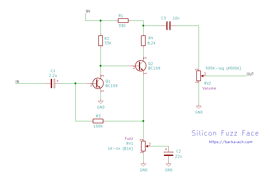
The FF circuit is rather simple: 4 resistors, 3 caps, and2 transistors. Seems like pretty simple stuff, and in principle it is, but there is plenty of black magic and mystery associated with a good sounding Fuzz circuit, and it takes a lot of effort to get the things sounding just right.
I'm Trying To Make A Fuzz Guitar Pedal. I'm Following A Instructables Tutorial But I Am A Bit Stuck On The Circuit Side Of Things. I Have All Potentiometers, Switches And Audio
The gain (Hfe) and leakage current inconsistency of the germanium transistors (the sound signature of this pedal) and the lack of ability/will to use the right componentscould make a huge impact on the tonal heart. The circuit layout in a pedal with a huge gain like this is critical and the component selection will leave its footprint on the sound.
Compiling all the knowledge and experiencethat we have nowadays about the Fuzz Face, we have designed this project that tries to bring the good old classic fuzz tone using modern and controlled technologies:
We ensure that the signal path is the same as in the 1966 FF vintage pedal. All the other features (true bypass, LED, quality components, polarity protection, turrets, power supply capacitor, etc) will not change the sound of it and enhance thequality and performance of the pedal.
Technology Of The Fuzz Face
The Germanium Fuzz total voltage gain is around 48dB matching the simulation. The pedal response has a low-frequency roll-off around 50Hz due to the two high-pass filters created by C1 and the Input Impedance and the combination of C3&RV2. There isn't any low pass filter in the circuit: in the treble side of the frequency response, the line extends flat to the limits of the measuring system. Not attenuating the high-freqs makes this pedal so rich harmonically, in the left image you can see all this harmonics when the pedal clips.
In the image below you can check how the Germanium Fuzz reacts to a sinusoidal input signal. It's interesting to see how the asymmetrical happenshapens first to the positive semicycle of the signal and how extremely distorted can get the fuzz output signal.
Note :In the beginning is difficult toapreciatethe change in the input signal because the level is so low that the oscilloscope cannot capture theamplitude change.
How Do You Calculate Input And Output Impedance Of A Pedal?
However, in order to reduce any excess of unwanted noise, two optional 100pF Miller capacitors (Cx) from base-to-collector on both transistors could be placed. This caps will limit the high-frequency response of the pedal and keep under control the hissing noise.
It is crucial to select the right transistors in order to archive the best sounding box. Germanium transistors tend to have high leakage current and an inconsistent gain value (Hfe). After years of experimentation and listening, it is agreed that the best match uses a low gain in the first stage (Hfe=80 approx.) and a high gain in the second stage (Hfe=120 approx.). Why is this? well if you use this values, the circuit bias points will look like this:
On the left image, the most important bias points are VC1=-0.5 to -0.7v and VC2=-4.5V, these values make the effect to sound fantastic. Using a Q1 and Q2 with the gains specified on the left image, the circuit will be biased to that points.
Arbiter Fuzz Face Clone
As we mentioned before, theses perfect AC128 120/80 Hfe transistors were long time discontinued. There is no source for them anymore and the only solution for builders is to pay astronomical prices for NOS, to buy big batches of similar transistors and try to find if it any left that meets the requirements, and try to avoid the re-labeled, fakes in that journey.
Instead of using the perfect and difficult-to-find transistors to get the circuit biased right, we can use almost any high-gain germanium PNP transistor (Hfe>50) and with the help of 2 trimmer resistors get the circuit perfect biased (right image). By doing this, we will create the same conditions for the transistors as if they were the perfect ones. Dunlop discovers this fact later on andincludes a trimmer on VC2in order to adjust it to -4.5V.
The first FF's manufactured in the UK used the AC128, a 45-165 Hfe European germanium PNP transistor, cheap/common at that time (later on replaced by the Newmarket NKT275). After this earlygermanium years, the production switched to the modern, temperature independent, and more stable silicon transistors like theBC108C, BC109C, and BC209C.
Simple Fuzz Pedal Using Breadboard
The classic 60's/70'ssoftdistortion Fuzz Face pedals (the ones used by Jimi Hendrix) used germanium transistors, but all the parts mentioned above (AC128, NKT275, SFT363E) were a long time ago discontinued. There is noofficialsource of transistors for this pedal anymore, the only way to obtain this parts is using specific online suppliers(Smallbear, etc), eBay, Amazon, repair shops, and surplus outlets.
Russian Germanium Transistors:For this project, we are going to use Germanium PNP transistors. They were manufactured back in the old USSR Soviet days, they are under military specifications that make them good, with a consistent gain and not leaky incurrent.
Thanks for reading, all feedback is appreciated This email address is being protected from spambots. You need JavaScript enabled to view it.How to build a basic Fuzz Face clone from scratch and turn it into a ‘boutique’ version with precision biasing, transistor switching and more.
Using A Solderless Breadboard
There are plenty of pedal kits out there, but something as simple as a vintage style fuzzbox can be built from scratch, allowing you to learn more about the circuit and make modifications to optimise tone and versatility along the way. Fuzz Face lore is awash with snake oil and there are units that sound mediocre and even pretty terrible as well as those mythical ‘golden’ examples that sound incredible.
Happily, knowledgeable replica builders have had decades to analyse this relatively simple circuit and develop a clear understanding of the variables that distinguish the best from all the rest. Many have kindly shared their findings, effectively demystifying the Fuzz Face in the process.
Here I’m showing you how to build a basic Fuzz Face from scratch and exploring how to make the circuit sound exactly as you want it. I’ll also be building a more advanced version with switchable transistors and some other boutique tweaks.
Fuzz Central Arbiter Fuzz Face
Let’s first distinguish between the two Fuzz Face eras. Arbiter Electronics Ltd began making Fuzz Faces in 1966 using NKT275 PNP germanium transistors. NKT275s can sound wonderful, but their sonic quality is notoriously inconsistent and their performance varies depending on ambient temperature. Arbiter merged with Dallas Electronics Ltd around 1968, and by the end of that year, Fuzz Faces were being made with NPN silicon transistors.
PNP stands for positive/negative/positive, and NPN stands for negative/positive/negative. Without wishing to get too far into the world of transistor manufacturing, they all have a ‘sandwich’ type construction. The middle (base) layer of PNP transistors is negative and the outer layers (emitter and collector) are positive. In NPN transistors, the polarity is reversed; the base being positive, and the emitter and collector both negative.
Sonic differences between germanium and silicon aside, this is important. PNP Fuzz Face circuits are not compatible with power supplies running a line of modern pedals because the positive is grounded rather than the now-conventional negative. PSUs with electronically isolated outputs may work, but it’s not ideal, and many vintage and vintage-style Fuzz Face owners resign themselves to using batteries. To keep things straightforward, I’m starting with a NPN silicon transistor Fuzz Face that can be powered using a standard supply.
Guitar Circuits And Schematics: Fuzzi, Amps And Other Effects
If you think the price of old-stock tubes borders on the insane, try researching vintage transistors. This is especially true of ‘holy grail’ transistors that were used in classic treble boost, wah and fuzz pedals. My advice is not to get too drawn into all that and be wary of buying expensive NOS transistors without guarantees from the seller that they aren’t leaky and have adequate gain.
NPN silicon resistors used in Fuzz Faces include BC108C, BC109B, BC109C, BC183L and BC209C. You can find these online from components suppliers such as rapidonline.com and cricklewoodelectronics.com – in fact, you can probably get all the parts for this project from either of these outlets.
For a thorough analysis of the germanium and silicon Fuzz Face circuits, visit this site – there’s also some down-to-earth advice on transistors and a very simple little circuit for testing transistors for leakage and gain. I use it to test my transistor stock and find that some are leaky. This isn’t unusual and the leaky ones shouldn’t be used. Fortunately, I do find a few that don’t leak and I write the gain rating of each on the side of the casing.

Circuits Of Guitar Fuzz Box And Fader Control
It’s easy to find printed circuit boards for PNP and NPN Fuzz Face circuits, but
0 Response to "Fuzz Guitar Pedal Schematics"
Posting Komentar